May 2006
NAD C372
Integrated Amplifier: Measurements
All amplifier measurements are performed
independently by BHK Labs. Please click to learn
more about how we test amplifiers there. All measurement data, including graphical
information displayed below, is the property of SoundStage! and Schneider
Publishing Inc. Reproduction in any format is not permitted.
- Measurements were made at 120V AC line voltage with both
channels being driven; measurements made on left channel unless otherwise noted. The
volume control was set to the reference position to produce 5W into 8 ohms with 500mV
input unless otherwise noted.
- This integrated amplifier does not invert polarity with or
without tone controls engaged.
- AC line current draw:
- at idle: 0.59A
- in standby: 0.04A
- Input sensitivity for 1W output into 8 ohms, volume at
maximum: 35.0mV
- Output impedance at 50Hz: 0.035 ohms
- Gain, output voltage divided by input voltage, volume at
maximum: 80.8X, 38.2dB
- Output noise, 8-ohm load, 1k-ohm input termination, Lch/Rch
- Volume control at reference position
- wideband: 0.40mV, -77.0dBW / 0.37mV, -77.7dBW
- A weighted: 0.11mV, -88.2dBW / 0.078mV, -91.2dBW
- Volume control full clockwise
- wideband: 0.62mV, -73.2dBW / 0.54mV, -74.4dBW
- A weighted: 0.14mV, -86.1dBW / 0.095mV, -89.5dBW
- Volume control full counterclockwise
- wideband: 0.38mV, -77.4dBW / 0.34mV, -78.4dBW
- A weighted: 0.058mV, -93.8dBW / 0.089mV, -90.0dBW
Power output with 1kHz test signal
- 8-ohm load at 1% THD: 189W
- 8-ohm load at 10% THD: 228W
- 4-ohm load at 1% THD: 185.5W
- 4-ohm load at 10% THD: 228.7W
General
The NAD C372 is a medium-power solid-state integrated
amplifier. Overall gain of the unit is about normal for an integrated amplifier. Of
interest, and not always the case, is that the overall input/output polarity is maintained
as non-inverting when the tone controls are engaged.
Chart 1 shows the frequency response of the amp with
varying loads. The high-frequency response is quite wide. with an approximate 3dB down
point of 200kHz. Output impedance, as judged by the closeness of spacing between the
curves of open-circuit, 8-ohm, and 4-ohm loading, is quite low in the audio band. The
usual NHT dummy-load curve is not shown as the variations in the response would not show.
The variation with the NHT dummy load in the audio range is of the order of +/-0.05dB -- a
negligible amount. The frequency response was quite independent of volume-control setting.
Chart 2 illustrates how total harmonic distortion plus
noise vs. power varies for 1kHz and SMPTE IM test signals and amplifier output load.
Unusual for a solid-state power amplifier, the attainable power is about the same for 4-
and 8-ohm loads. Amount of distortion is low right up to clipping -– the behavior of
most solid-state power amplifiers.
Total harmonic distortion plus noise as a function of
frequency at several different power levels is plotted in Chart 3. Amount of rise in
distortion at low and high frequencies is low except at the low-frequency extremes at the
150W level where the power supply just can’t supply the steady-state power in the
4-ohm loads. This didn’t happen with the 8-ohm loads.
Damping factor vs. frequency is shown in Chart 4 and is of
a value and nature typical of many solid-state amplifiers being high up to about 1kHz and
then rolling off with frequency.
A spectrum of the harmonic distortion and noise residue of
a 10W 1kHz test signal is plotted in Chart 5. The magnitude of the AC-line harmonics are
low and simple, and intermodulation components of line harmonics with signal harmonics are
also low. Signal harmonics consist of a tapering off spectrum of even and odd harmonics.
| Chart 1
- Frequency Response of Output Voltage as a Function of Output Loading |
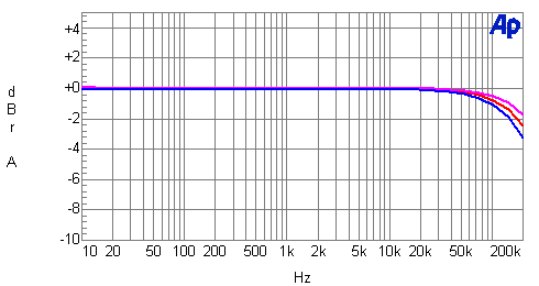
Red line: open circuit
Magenta line: 8-ohm load
Blue line: 4-ohm load
| Chart 2 - Distortion as a Function
of Power Output and Output Loading |
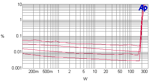
(line up at 10W to determine lines)
Top line: 4-ohm SMPTE IM
Second line: 8-ohm SMPTE IM
Third line: 4-ohm THD+N
Bottom line: 8-ohm THD+N
| Chart 3 - Distortion
as a Function of Power Output and Frequency |
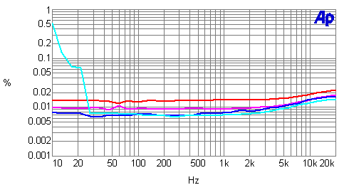
4-ohm output loading
Cyan line: 150W
Blue line: 70W
Magenta line: 10W
Red line: 1W
| Chart 4 - Damping Factor
as a Function of Frequency |
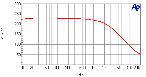
Damping factor = output impedance divided into 8
| Chart 5 - Distortion and
Noise Spectrum |
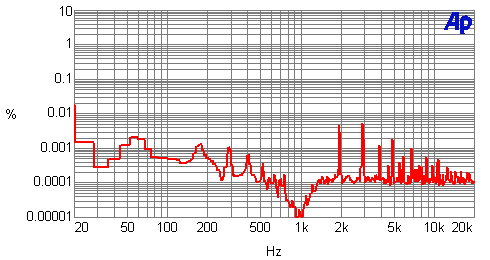
1kHz signal at 10W into a 4-ohm load
|
![[SoundStage!]](../titles/sslogo3.gif) Home Audio
Home Audio