January 2006
Rogue Audio
Metis Preamplifier: Measurements
All preamplifier measurements are performed
independently by BHK Labs. Please click to
learn more about how we test preamplifiers there. All measurement data, including
graphical information displayed below, is the property of SoundStage! and
Schneider Publishing Inc. Reproduction in any format is not permitted.
- Measurements were made at 120V AC line voltage.
- Gain:
- Line section, Lch/Rch = 4.62X, 13.3dB / 4.36X, 12.8dB
- Phono section (at 1kHz) = 76X, 37.6dB
Output noise versus bandwidth and volume-control position,
wideband/A weighted:
- Volume control turned CCW, wideband, Lch/Rch = 0.23mV / 0.24mV
- Volume control turned CCW, A weighted, Lch/Rch = 0.032mV / 0.060mV
- Volume control at reference (unity gain), wideband, Lch/Rch = 0.24mV / 0.27mV
- Volume control at reference (unity gain), A weighted, Lch/Rch = 0.037mV / 0.058mV
- Volume control turned CW, wideband, Lch/Rch = 0.74mV / 0.75mV
- Volume control turned CW, A weighted, Lch/Rch = 0.057mV / 0.058mV
Phono referred input noise, 1k-ohm source impedance:
- Wideband, Lch/Rch = 11.4µV / 3.0µV
- A weighted, Lch/Rch = 3.7µV / 0.91
µV
AC line current draw at idle: 0.27A
Output impedance at 1kHz:
- Line section = 720 ohms
- Phono section (at fixed outputs) = 39 ohms
Input impedance at 1kHz:
- Line section = 150k ohms
- Phono section (paralleled with 150pF) = 47k ohms
Phono overload at 1kHz = 106mV
This preamplifier line section inverts polarity; the phono
preamp section does not invert polarity.
General
The Rogue Audio Metis preamplifier utilizes two octal-based
6SN7 tubes in its line-section signal circuitry. The phono circuitry is implemented with a
dual op-amp.
Chart 1 shows the frequency response of the Metis for both
channels with the volume control set for unity gain and with instrument and IHF loading.
With the IHF load, the high-frequency response is unaffected, but the low-frequency
response starts to roll off due to the size of the output coupling capacitors and the
relation to the 10k IHF loading. Generally, this preamp’s high-frequency response is
at its worst at full volume and gets better as the volume is turned down.
At full gain with the volume fully up, Chart 2A shows the
most high-frequency roll-off. With the volume control set at an attenuation of about
–30dB, which is where the volume would likely be set for typical listening, the
response is much flatter, as shown in chart 2B. Volume-control tracking between channels
was within 0.8dB down to –60dB attenuation. Note that in chart 2B tracking between
channels is particularly close.
Chart 3 shows how THD+N (total harmonic distortion plus
noise) varies as a function of preamp output level. The volume control is set for unity
gain. In this particular case, the curves were only a little different for the three test
frequencies of 20Hz, 1kHz, and 20kHz, and for instrument and IHF loading. This is good for
the distortion to be essentially independent of frequency and loading. The curve shown in
Chart 3 is typical for the various frequencies and loading.
With the volume control again set for unity gain, a plot of
the 1kHz distortion at 0.5V output is shown in Chart 4. Results for this test were about
the same for instrument or IHF loading.
Because this preamp has no tone controls, there is no Chart
5 to display the tone-control characteristics.
RIAA equalization error for the phono preamp is plotted in
Chart 6. The two channels differ above 1kHz, but the overall error is quite acceptable.
Phono THD+N versus output voltage and frequency is shown in
Chart 7 for instrument loading. With the IHF load, instability set in between 2-3V, which
prevented getting the curve data for that condition.
| Chart 1 - Frequency
Response at Unity Gain with IHF and Instrument Loading |
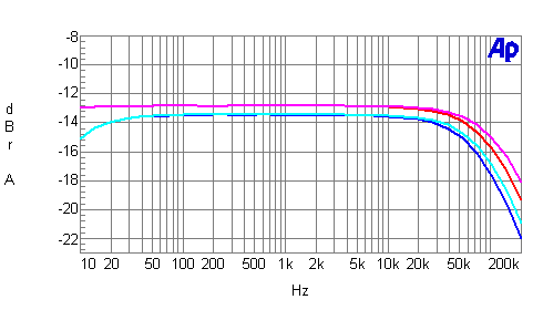
IHF loading
Blue line = left channel
Cyan line = right channel
Instrument loading
Red line = left channel
Magenta line = right channel
| Chart 2 - Frequency Response as a
Function of Volume Control Setting |
Chart 2A - volume at maximum
(0dB)
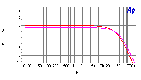
Instrument loading
Red line = left channel
Magenta line = right channel
Chart 2B - volume at -31dB
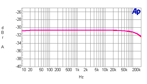
Instrument loading
Red line = left channel
Magenta line = right channel
| Chart 3 - Distortion
as a Function of Output Voltage and Frequency |
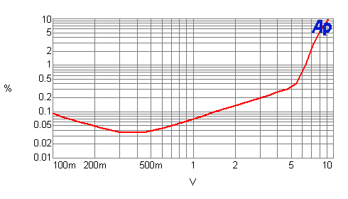
Instrument loading
Red line = 20Hz, 1kHz, 20kHz
| Chart 4 - Distortion and
Noise Spectrum |
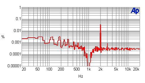
Red line = spectrum of 1kHz test-signal distortion and AC-line harmonics at 0.5V input and
output
| Chart 6 - Phono-Stage RIAA
Equalization Error |
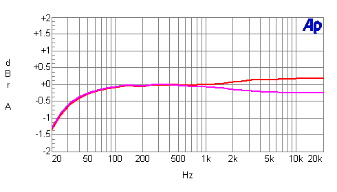
Instrument loading
Red line = left channel
Magenta line = right channel
| Chart 7 - Phono-Stage
Distortion vs. Frequency and Output |
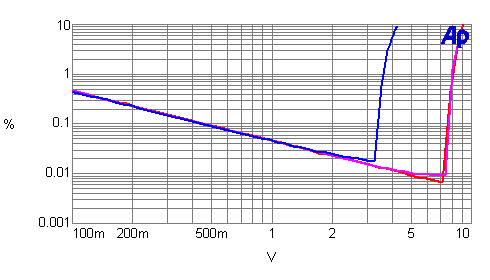
Instrument loading
Red line = 1kHz
Magenta line = 20Hz
Blue line = 20kHz
|
![[SoundStage!]](../titles/sslogo3.gif) Home Audio
Home Audio ![[SoundStage!]](../titles/sslogo3.gif) All Contents
All Contents


