General
Einstein's The Tube line-level preamplifier is definitely a
departure from the normal tube preamp. This unit doesn’t have a selector switch as
such, but utilizes a separate tube circuit for each input. The outputs of these input
tubes are all summed together and the selected input is chosen by enabling the tubes’
heater supplies. Ten of the 19 tubes of the unit are used for this purpose. The remaining
nine tubes are for the main line section. The outputs of the test unit were balanced XLR
only.
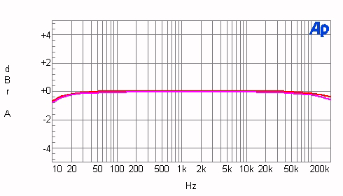
Chart 1 shows the frequency response of The Tube with the
volume control set for unity gain for 0.5V input with instrument and IHF loading. In this
chart, only the left channel is shown to show the effect of the IHF loading, which is
pretty negligible. The two channels are tracking within 0.05dB at this point on the volume
control. The bandwidth of this unit (as defined by the -3dB points) is less than 10Hz to
over 200kHz. With a 600-ohm load, the frequency response was the same and dropped about
1.4dB, yielding an output impedance of about 105 ohms. This is pretty amazing performance
for a tube circuit. After studying the circuitry, it turns out that the output stage
utilizes four triode sections of two 6922 tubes paralleled per output phase. The number of
tubes and the circuit topology explain the 600-ohm driving ability.
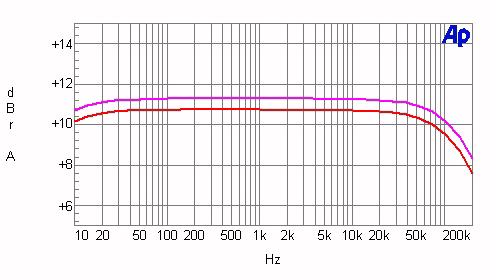
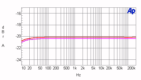
In charts 2A and 2B, the frequency response of the preamp
is shown for both channels with the volume at maximum and at a typical listening position
(20dB below unity gain). The high-frequency response does change a bit with volume-control
position (not unusual), having the most high-frequency roll-off at the full volume
position, which would never be used in normal circumstances. At the lower level of -20dB
below unity gain, the high-frequency response is quite flat and remains so for further
volume attenuation. Volume-control tracking is very good over the working range, generally
being better than 0.5dB.
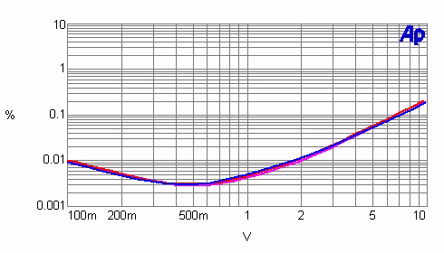
Chart 3 shows how total harmonic distortion varies with
input level and frequency for both IHF and instrument loading. Again, we have a design in
which the distortion vs. level is virtually the same for frequencies from 20Hz-20kHz and
with instrument and IHF loading. For clarity, the data shown is for the right channel for
instrument loading. Further, to my amazement, the distortion with a 600-ohm load was just
a little higher than with the instrument load! This would definitely break the back of a
usual tube circuit.
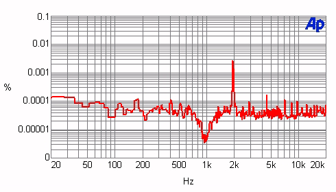
A spectrum of the distortion and noise residue of a 1kHz
test tone at 0.5V output with IHF loading is plotted in Chart 4. AC-line hum harmonics
here are very low. The signal frequency harmonics consist of a dominant second harmonic
and some much lower-level higher-order components.
If I can put in my two cents’ worth, I listened to The
Tube and found it to be one of the best-sounding preamps that I have had the pleasure of
putting in my system.
![[SoundStage!]](../titles/sslogo3.gif) Home Audio
Home Audio ![[SoundStage!]](../titles/sslogo3.gif) All Contents
All Contents