![[SoundStage!]](../sslogo3.gif) Max dB with Doug Blackburn Max dB with Doug BlackburnBack Issue Article |
| July 2000 WARNING: This installment of Maximum dB describes a component modification. Modifying any electronic device including, but not limited to, the DVD player described in the article can present serious fire, electric shock, and other safety hazards. In addition to damaging yourself, undertaking this type of DIY (do-it-yourself) project may result in permanent damage to your equipment and will likely void any applicable manufacturer’s warranties. As with all DIY articles featured in SoundStage!, the information presented is purely for the entertainment of the SoundStage! reader. SoundStage! does not suggest, recommend, or encourage any of its readers to modify their own equipment and can not and does not assume responsibility for incidental or consequential damage to equipment or injury to persons engaging in such modifications. In addition, SoundStage! can not and does not expressly or impliedly warrant or guarantee that the modifications described by dB in this article can be safely implemented or that such modifications will necessarily result in improved performance of the electronic device. Modifying a DVD/CD Transport or Player -- Part Two Chassis and transport damping
Apply the damping material to the bottom, sides
and top of the chassis. Watch for overlaps of chassis panels that can get stuck in the
rope caulk. Remove the transport (four screws) and remove the clear plastic "keeper" for a flat cable on the bottom of the chassis. You will not be reinstalling this piece of plastic. The flat ribbon cables just pull out of the female connector. Pull straight up to remove the ribbon cables. There is no lock or latch on these connectors. Hold the flat cable on the bottom of the chassis of the DV-525 in place using beads of rope caulk or similar along its edges in several places
Apply damping material to the bottom of the transport drawer. Pack all cavities with damping material while checking repeatedly for proper clearance. Use caution when disassembling the transport; there is no rush. You can completely remove the drawer if you are careful. Release the "latch" at the rear of the drawer to let it come all the way out.
Better RCA jack for digital coax Remove the rear panel of the DV-525 so you can hold it in your hand. Locate the solder holes for the digital coax jack (three solder points). Remove the solder so the existing cheap RCA is loose and ready to come out. Remove the original plastic RCA after you are certain you know where to connect the center conductor, the shield and the chassis ground. Write this on paper so you can't forget. And do not guess at which connection is which. Measure the connections with a meter if there is any question about which connection is which.
Solder two leads from replacement RCA to proper solder points. Solder a third wire (green in this case) to the third connection point (ground) and connect the loose end to chassis ground inside the DV-525 somewhere. If you want to do something extra here, you might consider replacing the RCA with a true 75-ohm BNC connector. Even if only one end of your digital cable has BNC, the cable will still sound better than if it had two RCAs. Internal RFI/EMI shielding
For this, use copper tape to make the ground planes. I use 1/4" tape because it fits a variety of ICs, although you must use multiple widths to cover large ICs. This is not a problem if you bridge solder across separate strips of tape so that all are joined electrically. I get 3M copper tape from MCM Electronics by mail, but there are many sources. You should tack the edges of the copper tape to the IC with a suitable cement -- circuit-board cement or radio and TV cement are the best products to use. The glue on the copper tape is not that sticky and it will not secure the copper exceptionally well, especially when we start soldering ground wires to the copper tape. The last step for completion of the ground plane mod is to locate a suitable chassis ground that you can reach with relatively short lengths of wire which will run to each ground plane you created. Solder a ground wire to each ground plane and connect the other end to the chassis; this mod is complete. In the photo below you can clearly see four ground planes on the four large ICs. All the ground wires connect to a screw through the chassis at the lower left in the photo. One IC (black, lower right corner of circuit board in the photo) was left without a ground plane due to the presence of a conductive surface on the outside of the IC. Another shielding opportunity not shown in this photo is to wrap copper shielding tape or copper shielding fine mesh screen around all the ribbon cables then attach a ground wire to the copper shield you created. This will stop radiation into or out of the ribbon cables. Those pesky steel jumpers on the circuit boards Replacing every shiny steel jumper wire on every circuit board will improve the sound quality. Use a solid-core copper wire of similar diameter. This can be a daunting task in some products due to the vast number of steel jumpers. If you feel the need to limit the number of them you replace, concentrate on the power-supply circuit board and the analog-output circuit. However, if you are going to use the product as a disc transport, replacing the steel jumpers in the analog output section would be a waste of time. The Pioneer DV-525 has a large number of these jumpers on the output board, but none of any significance on the power-supply circuit board. So the DV-525 is not a good candidate to benefit from replacing the steel circuit-board jumpers. Other brands or models may be loaded with replaceable jumpers in worthwhile-to-change locations. Laser mechanism -- anti-reflection and aperture paint
In the photo you see a view of the laser mechanism with a close-up of the laser in the inset at the lower-right corner. Note that the olive-drab paint covers what was a shiny metal part that surrounded the laser. While the entire laser mechanism is pretty easy to spot, you can't actually see the laser itself. The only part of the laser you can see easily is the lens, which has a blue-ish look to it, especially toward the center. Lasers that read reflected light from a nearby surface work better if they have an aperture. Virtually no CD or DVD player leaves the factory with an aperture. But not to worry; even if you do not have a steady hand, you can paint an aperture around the circumference of the laser lens. You will paint the vertical shoulder and the flat top edge of the laser lens and just barely start up onto the curved surface of the lens. The lens is connected to a servo system that can move it very rapidly up and down and left to right to keep the laser centered on the data even if the disc is wobbling a little or if it is off-center. Don't worry if the lens moves a little when you are painting it. A large slip will probably permanently disable your laser mechanism. The only remedy is replacement of the laser mechanism, which is likely to cost $75 to $150 in mass-market products. So if you don't have a lot of practice with a small paint brush and model enamel, practice on the end of some of those round-ended ball point stick pens before you paint on your laser lens. I take no responsibility for your not understanding what to paint and what not to paint around the laser lens. If you do not intuitively understand that you want to paint the outer circumference and keep 85% of the central (thickest part) of the lens completely clear of paint, do not attempt this yourself; get help. This isn't a massively big deal sonically, so don't over-reach your abilities trying to do this one anticipating a huge sonic payback. The payback is there, but it is small. You'll notice it, but others probably won't. Devil in the details Remove the plastic feet completely. Level the transport for optimum performance. Experiment with good-sounding feet under the player/transport. A better-quality back-panel S-Video connector will improve image quality a little. Eliminate nylon circuit-board standoffs; ceramic standoffs sound better. Treat all internal and external electrical connections in the transport/player with Caig Labs ProGold or ProGold GXL (GXL lasts twice as long -- figure a decade!). Cautionary tale Reassemble the DV-525, let it warm up for 30 minutes and have a listen to nice, pure digital sound. A warning: If you think the power-supply PCB could stand more mods and you replace other electrolytic capacitors or add film-and-foil bypasses or if you replace other diodes, you will probably disable the power supply. Most mass-market DVD players and even some high-end DVD players are using switching power supplies that are tuned. If any of your tweaks change the tuning of the power supplies, you can disable one or more power-supply voltages. The diode replacement and filter-cap addition and replacement described above are performed on portions of the power supply before the tuned switching takes place and cannot upset the operation of the power supply in any way. Going another mile While the internal mods are certainly effective, there's nothing like completing the package with some accessorizing. This will drive performance so far up the ladder you have to wonder what could possibly be left from purely a sonic perspective. First, you'll want an AudioPrism Wave Guide on the power cord and on the digital coax cable -- $99 each. Very effective in this application. Extends the sonic envelope deeper into ultra-refined with a big spatial feel. A Richard Gray's Power Company device providing AC adds another level of background silence and shimmery rich detail. A Power Plant P300 offers similar improvements, though it is slightly less shimmery-rich and perhaps a little more focused and detailed. A LaserBase isolation system removes a cloud of confusion you don't even realize is there until it's gone -- not like cleaning the windows and screens, like removing them completely. Use a disc mat. My current preference is the Statmat, though it is a bit of a pain and perhaps a little too delicate. Use a disc treatment. Audience's Auric Illuminator is as much of an improvement as many hardware upgrades. There you have it -- with a little ingenuity and creativity you can get a lot more performance out of budget-priced equipment. Good luck and have fun! ...Doug Blackburn
|
|
| All Contents Copyright © 2000 SoundStage! All Rights Reserved |
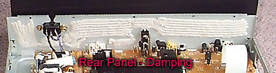 Applying
the damping material uniformly and neatly actually is less effective than being a little
haphazard. The varying thicknesses and imperfect placement actually improve the damping
effect you get by spreading resonances out rather than allowing them to accumulate at
specific frequencies.
Applying
the damping material uniformly and neatly actually is less effective than being a little
haphazard. The varying thicknesses and imperfect placement actually improve the damping
effect you get by spreading resonances out rather than allowing them to accumulate at
specific frequencies.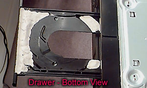 Apply damping
material to the bobbin and square transformers on the power supply PCB (three total
devices). See the three power-supply photos above for examples of damping the small
transformers on the power supply PCB.
Apply damping
material to the bobbin and square transformers on the power supply PCB (three total
devices). See the three power-supply photos above for examples of damping the small
transformers on the power supply PCB.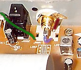 Replace the original RCA with
any good-quality RCA; the replacement in the photo is gold with a blue wire to the center
conductor, a dark-brown wire (hard to see, short, just to the right of the RCA), and a
green wire to the chassis.
Replace the original RCA with
any good-quality RCA; the replacement in the photo is gold with a blue wire to the center
conductor, a dark-brown wire (hard to see, short, just to the right of the RCA), and a
green wire to the chassis.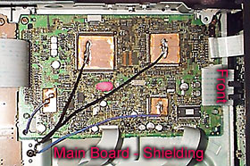 You can gain a small improvement in sound quality by
installing a small ground plane on each large integrated circuit. This keeps internal RF
from escaping the IC and prevents external sources from entering the IC. More ambitiously,
you could fabricate a ventilated ground plane that covers the entire main circuit board. I
didn't have time for that, so I used the "quick fix."
You can gain a small improvement in sound quality by
installing a small ground plane on each large integrated circuit. This keeps internal RF
from escaping the IC and prevents external sources from entering the IC. More ambitiously,
you could fabricate a ventilated ground plane that covers the entire main circuit board. I
didn't have time for that, so I used the "quick fix."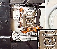 Use flat black, flat
olive-drab or other suitably dark, non-reflective paint to cover any shiny surfaces around
the laser. Use plastic model enamel readily available at any hobby shop that sells plastic
car, airplane, or ship models or model railroading supplies. While there, get a decent,
relatively small, but not minutely small, camel hair paint brush and a small bottle of
brush cleaner to save your brush so you can use it in the future.
Use flat black, flat
olive-drab or other suitably dark, non-reflective paint to cover any shiny surfaces around
the laser. Use plastic model enamel readily available at any hobby shop that sells plastic
car, airplane, or ship models or model railroading supplies. While there, get a decent,
relatively small, but not minutely small, camel hair paint brush and a small bottle of
brush cleaner to save your brush so you can use it in the future.