![[SoundStage!]](../sslogo3.gif) Max dB with Doug Blackburn Max dB with Doug BlackburnBack Issue Article |
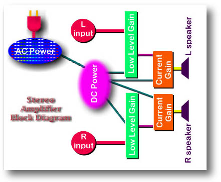
| September 1998 The Amplifier: What’s Inside? What Makes a Difference? What’s Overlooked? – Part One This month starts what will be a two-part look at the amplifier and how it does what it does -- block by block, component by component. I’m expecting to do this in a way that is useful for beginners as well as being thought-provoking for you amp experts, including amp designers, out there. The first thing to do is have a look at the amplifier block diagram. In the illustration, all the inputs are red. The outputs are yellow. The inputs are AC power, left-audio-in from the preamp and right-audio-in from the preamp. The outputs are the signals going to the loudspeakers. Easy enough.
Within each subsystem in the amplifier you have a number of components. Here is a summary of those components: AC power
DC power
Low-level gain stages
Output stage
Mechanical package
You can find circuit diagrams for tube amplifiers in reference books that are 50 years old or more. If you constructed that circuit using high-quality parts that are available today, you’d actually have an amp that wouldn’t sound too bad -- perhaps not an ideal state-of-the-art sound, but you’d be pretty well along the way. Doing a solid-state amp from scratch is not much different. Select the output devices carefully, combine with other good resistors and capacitors that are available today and you could get some pretty good sound from even older circuits. However, building a high-end version of one of these amplifiers with performance pushing the limits of what is possible as we look at the change in millenniums is a lot more complicated. A lot more thought needs to go into the circuit, the parts, the specs, the subjective performance, the appearance, and the mechanical package. In spite of the attention to some details in high-end amplifiers, there are things that could be done to improve amplifier performance that are mostly or completely ignored by designers and manufacturers. Let’s start the subsystem-by-subsystem look at amplifiers, the AC-power subsystem first. AC power If your amplifier is a tube amp, the first thing you have to worry about is AC line voltage. Voltages in the amp increase if the AC line voltage is high. This leads to operating the tubes outside of their designed range because tube voltages are higher than the AC line voltage. Step-up transformers raise the line voltage. Let’s say the designer makes the amplifier to operate best with a 117v AC line. Someone living where the line voltage is 125v would see that increased to 375v by a 3X step-up transformer. The amp designer was expecting 351 volts (117v times 3). This scenario magnifies the difference in the line voltage. Some tube amps take steps to prevent this kind of difference from affecting the voltage supplied to the tubes, but many do not. Higher line voltages are not the only problem. If you live in some areas of Europe or some areas of the US (notably in the NYC metropolitan area), lower-than-ideal AC line voltages can be a frequent problem. This can also put tube amplifiers outside of their ideal operating ranges. A serious commercial product needs to be relatively immune to these line-voltage shifts. How these high or low AC line voltages are dealt with is critical. You have to worry about the whole world -- different AC voltages and different amounts of AC line voltage drift. Solid-state amps have less trouble with line voltage stability, primarily because their operating voltages are lower than the AC line voltage, which makes the differences in AC line voltage smaller when stepped-down though the power transformer. The power transformer. I dealt with a lot of benefits and shortcomings of toroid power transformers and EI frame transformers in a Maximum dB column a couple of months ago. I won’t go into great detail again. However, the mounting method and location for the transformer is one of the clues to a great-sounding amp. I’ll discuss transformer mounting methods in part two of this article, next month. One thing I didn’t talk too much about in the earlier Maximum dB column about transformers was the strength and direction of the magnetic field coming off the transformer. The large square EI frame transformer has a large but not terribly strong magnetic field coming out the curved "bell" ends of the transformer in broad circles with the transformer windings (under the "bells" that cover the windings) acting as the anchor point. There is little or no field radiated by the fat metal laminations. You do need to be careful where the magnetic field of the EI frame transformer is aimed. You want to keep it away from the low-level circuit boards and from the input RCAs and wiring. The toroid, a round donut-looking transformer, has almost no magnetic field radiating out from it except along an almost straight line right through the hole in the center of the toroid. Within that center hole and extending up and down (toroids are almost always mounted flat because of this magnetic field) from it is one massively strong magnetic field. It has the same relative strength as the weaker but larger-sized field that radiates from the EI frame transformer, but it is so concentrated by the shape of the toroid transformer that that the density of the flux energy in the field radiating from a toroid is very high indeed. The larger the toroid, the stronger this radiated field. Imagine a miniature javelin going through the hole in the toroid transformer; this is a pretty good representation of the radiation pattern of the magnetic field (though the field spreads out a bit as you get farther away from the toroid). Placing some other component above or below an amplifier with a large toroidal transformer inside is asking for trouble. You could get hum or otherwise degrade the sound. Only a large amount of ferrous material, like cast iron, above and below a toroidal power transformer will block the magnetic field. The aluminum or thin steel chassis in most audio components is virtually transparent to the magnetic field from the transformer. So are wood or glass rack shelves. Even the second chassis of another nearby component won’t reduce the strength of the magnetic field too much. Other than an inch-thick cast iron plate, the best defense against these strong magnetic fields from toroidal transformers is distance or placing other components beside the component with the toroidal power transformer rather than above or below it. Even the small toroid in a turntable or preamp power supply could induce hum in other components if they get to close to the javelin-like magnetic field radiating out from the hole in the center of the toroid. To change AC power to DC power, you use four diodes in a specific orientation called a bridge rectifier. To save money and speed up assembly you can use a rectifier module that has all four diodes in a single "package" with four leads coming off of it. Two leads are for the incoming AC and two leads are for the DC (with ripple) coming off the rectifier. How the rectification (converting AC to something close to DC) is done audibly affects what you hear coming out of the speakers. Standard diodes, which are the least expensive types, are about the worst-sounding devices, unfortunately. The next step up the rectification ladder is what is referred to as "ultra-fast-recovery" diodes. Costing five to seven times more than standard diodes, the ultra-fast-recovery diodes give components, including amps, a cleaner, faster sound. Background silence is darker, transients take on new life and there is significant improvement in perceived clarity. Unfortunately, ultra-fast-recovery diodes for amplifiers are sometimes hard to find in the high-current ratings needed, particularly for high-power solid-state amps. The next step up the rectification ladder is HEXFREDs, which are typically 7 to 12 times more expensive than standard diodes. HEXFREDs seem to expand the envelope of the improvements wrought by ultra-fast-recovery type diodes. It isn’t a completely revolutionary improvement compared to ultra-fast-recovery diodes, but there are small, worthwhile gains to be had. Fortunately, high-performance high-current HEXFREDs are getting more common and it should be possible to find HEXFREDs in almost any current rating you might need for an amplifier. But because of the cost of the parts compared to standard diodes, you don’t see HEXFREDs in many amps so far, but you should be seeing them almost everywhere. They are all advantage and no disadvantage for an audio amplifier sonically. The cost of the HEXFREDs is higher, of course, and the fact that you use four discrete HEXFREDs with eight leads in total instead of a single modular rectifier part with four leads makes assembly very slightly more time consuming. But this is for high-end amplifiers. We pay a pretty good penny for these amps, so they ought to include the best-sounding parts available. I’ll make a hastily thought-out estimate here: Using HEXFREDs in a power amplifier instead of standard diodes or a standard modular rectifier would add $150 +/- $50 to the retail price of most amplifiers. Double that estimate for a pair of monoblocks or for dual-mono amplifiers where there are two transformers and two rectifiers. The power cord is an integral part of the AC-power subsystem of the amplifier. Different power cords make a difference in the sound of the amplifier because each one is constructed differently and each one has different mechanical resonance properties. Materials, geometry (how the materials are physically laid out) and electrical properties account for about half of the sonic signature of a power cord. The other half of the "sound" of a cord comes from its mechanical resonance properties. (I’m being intentionally conservative here; personally, I think the mechanical resonance differences might account for 75% or more of the sonic differences between power cords.) To hear the effects of mechanical resonance on your own power cord (even the stock one that came with the amp) experiment with it. Raise it off the floor with styrofoam cups or cardboard or glasses or paperback books or blocks of wood -- all of these materials will sound a little different because they have different resonant properties. Next, have someone pinch the power cord near where it plugs into the amplifier while you are seated and listening to music. While you are listening to full-range music, have your assistant slide his fingers away from the amp (down the cord) while maintaining pressure on the cord. As the person’s fingers slide down the cord, you will hear the sound change; it usually is not subtle either. What you will hear is less emphasis on the midrange and a sliding emphasis going deeper and deeper into the bass region as the squeezing fingers get farther and farther away from the amp. Another test is to have your assistant support the power cord with a small block of wood. Have your assistant start with the wood block under the power cord, right near the IEC connector at the amp end. While the music is playing, something relatively full range, have your assistant slide the wood block farther and farther away from the IEC connector until the block is 3' or so away. You will hear an upper-midrange emphasis first, and as the block moves farther from the IEC connector, the emphasis slides smoothly down the frequency spectrum into the bass and deep bass, which is why you need some full-range music to hear what is going on in this experiment. Change the kind of wood used here and you’ll change the sound you hear -- each wood has a different sonic signature. For another mechanical tuning experiment, have your assistant hold the IEC connector shell at the amp end of the power cord lightly between their fingers. While you are listening to music, have your assistant slowly increase the squeezing pressure on the IEC connector (works better if the shell is hollow and not solid molded plastic, but will work even with the solid molded type). What you will hear is an increasing emphasis on the highs as the squeezing pressure is increased. If you don’t have an assistant available, a small adjustable C-clamp from the hardware store will work for this experiment if there is room for it around the IEC plug on the power cord/amp. These sonic changes from adjusting the squeezing force on the IEC connector are a result of mechanical-resonance changes in the power cord -- not anything magical, not anything mystical, not anything top secret. These experiments may not reveal sonic changes with certain kinds of power cords which are very heavily internally damped. Usually these cords will be rather large/fat and be constructed of layers of damping material and layers of conductors. These cords eliminate resonances to a significant degree. I can’t say that they necessarily sound better, but they do sound more consistent no matter where you place the cord or how you support it. Mike VansEvers is exploiting this mechanical resonance tuning of power cords in his new Pandora and Double Pandora (including higher-cost and -performance Reference versions) power cords which have sliding mechanical dampers on the cords and thumbscrew adjusters for IEC connector tension. A review of the Pandora power cords will be forthcoming. Mike is also creating and selling kits of wood blocks which have varying numbers and sizes to be used for system tuning. They aren’t only for power cords -- they work almost anywhere. You use the wood blocks to evolve the sound of your system over time. Using the different types and sizes of wood much as you would use different colors in a Crayola box or in an artist’s palette, you finely tune the sound of your system to be just where you want it to be. You don’t have to use Mike’s wood blocks either, and he’s the first one to admit it. Anyone can cut wood blocks and experiment. Mike’s kits are offered as a convenience to people who want to do the tuning without the hassle of locating the different woods, cutting them to size and sanding them to a uniform surface finish. While each wood has a different sonic signature, each size of block also has a different signature. Smaller and thinner sizes affect the highs more, while longer and thicker pieces affect the lower mids and bass more. Mike’s standard block is a little shorter and a little thicker than a 9v transistor battery. The smallest blocks he makes are a little thicker than half a stick of gum. The largest sizes go up to around 4" long (a little thicker than a 9v battery). After years of experiments, I believe everything you place on or under a power cord affects the sound because of mechanical resonance changes, not because of any significant electrical properties. This includes ferrites. I was once a major believer in the electrical/electronic benefits of ferrites’ ability to absorb RFI/EMI from the electrical field around the power cord. Today, while I believe ferrites still do that, I question whether the sonic change from using ferrites has anything to do with the absorption of RFI/EMI. On the other hand, I now know ferrites change the sound of the cord mechanically. You can slide a ferrite along a power cord and get the same sonic signature you get from squeezing the power cord or sliding a wood block along it. Fuses and circuit breakers are bad news for amplifiers. You really need them for safety in the event of component failures in the amp as well as for safety if a careless audiophile does something unexpected or unintended. However, fuses and circuit breakers generally sound bad. You want to hear how bad? If you amp has fuses, remove the fuses, wrap copper tape around the fuses and reinsert them. Alternatively, make temporary jumpers to bypass the fuses. (Standard disclaimer information: "Don’t try this without knowing what you’re doing," and "SoundStage! takes no responsibility for any damage caused by this experiment. So, don't do it then.") This is NOT something you should leave this way -- it is very dangerous to do so. If you are not familiar with the safety precautions you must follow to safely go inside a power amp to make changes like these, don’t even think of doing this experiment. The audible change from getting the fuses out of the circuit will be rather significant unless your amplifier manufacturer/designer has taken measures to reduce the audibility of the fuses. This is possible. A few amp manufacturers know how to do it, but most don’t. Those who do know how to do it consider it one of their proprietary design features. Since I learned how to do it from one of these few amp manufacturers, I am not at liberty to reveal the technique(s), unfortunately. Circuit breakers also don’t sound very good, with one exception. There is a rather expensive type of magnetic circuit breaker that sounds pretty good. Unfortunately, for larger sizes needed for power amplifiers, they are expensive. A single pair of good-quality magnetic circuit breakers would add close to $200 to the retail price of an amplifier. Double this figure for dual-mono amps or monoblocks. DC power Filter capacitors: We’ve been dealing with them for ages and amp manufacturers still miss something very significant. Having multiple different-sized filter capacitors always sounds better than having one huge capacitor or four (or six) smaller capacitors that are all the same size. This has to do with impedance differences in caps of various sizes. If you put one huge cap in as the filter, you are stuck with that cap working best within one specific range of frequencies due to the capacitor’s impedance characteristics. If you put four capacitors, all of the same size, you have the same problem but in a different range of frequencies. For that reason, spreading out the values of the filter capacitors makes all kinds of sense logically and sonically, but you rarely see any amp manufacturer doing this. You’ll see them use film and foil caps in parallel with the big electrolytics, which is definitely a good thing, but you rarely, if ever see them spread out the values of the caps to get better sonic performance across a broader frequency spectrum. What does this mean in practical terms? Let’s take an amplifier design that calls for 40,000uF of filter capacitance for each "rail" (the + and – voltage supplies in amplifiers are often called the "rails"). Some amp designers will opt for a single large 40,000uF capacitor and perhaps bypass it with a 2uF to 4uF film and foil capacitor. Another amp designer might select four 10,000uF capacitors then use somewhere between zero and four film and foil bypass capacitors. What you see in amplifiers today is almost always one of these two approaches. I’m going to recommend something different. A capacitor "array" that totals 40,000uF (or close to it) where none of the capacitors have the same value. The array might be made of a 37,000uF capacitor, a 4,700uF cap, a 470uF cap, a 47uF cap which could all be electrolytics. Then add 4.0uF, 0.47uF and 0.01uF film and foil caps in parallel. Simply having these different values of caps will make a big difference sonically. There is a small danger of setting up a "tank circuit" when using many different capacitors in parallel like this arrangement. However, this is pretty obvious if and when it starts happening, and a designer would know there is a problem immediately due to the increasing volume of the runaway oscillations, which are quite audible. A capacitor array like the one suggested is going to cost more to procure, cost a little more to assemble and a little more to do the original engineering. An array of capacitors like this would add surprisingly little to the retail price of an amplifier. $25 to $100 would do it for many amplifiers, depending on the capacitors selected and the prices the manufacturer could get. Double that cost for dual mono amps or monoblocks. I expect no credit whatsoever for the idea of the capacitor array. It has bee around for a long time. I just can’t figure out why something that offers better sound quality and is available for free (other than the parts/fabrication cost, of course) just sits on the table unused by designers who are supposed to know what they are doing. Internal wiring is an often-overlooked necessity. I’d venture to say that a majority of amps made today (perhaps 90%) don’t overly sweat the details of the internal wiring. They either use something of good quality but not audiophile, or use a branded audiophile wire, hook everything up and pretty much forget about it. The remaining 10% sweat this detail with significant effort. They may end up with two or three or four different kinds of wire in a component for each different job that needs to be done. Admittedly, you aren’t probably going to get huge changes from wire differences, but you can get meaningful ones. As in the power cords, the differences in the sound of various hook-up wires is not only caused by electrical properties, but by mechanical properties too. There are things manufacturers do to the wiring that improve safety, appearance, and shipability. Unfortunately, these things often degrade the sound of the amp. A certain inhabitant of paradise relates a story about one of the fabled high-end amp brands being significantly improved in sonics by removing wire ties used to bundle all the wires together. I have heard the same thing for myself. Pretty wire arrangements with everything all cinched up tightly together may look all German precision-engineered and spit-polished, but a freeform maze of separated wires will sound better, unless something needs to be a twisted pair or something like that of course. I don’t have too much to say about regulation and other types of filtering devices (like inductors) in the DC side of the amplifier power supply. These are mostly well implemented by most designers. Different amps use different approaches. The mechanical issues of how these devices are mounted can affect their sonic performance as much as their specifications and construction. One area under specification in some power amplifiers is the size of the traces on the power-supply circuit board. In some cases, the needed trace sizes are under-estimated. If that happens, you’ll notice an improvement in sound quality if you add parallel 18- or 20-gauge wires with the too-small circuit-board traces. This increases current-carrying capacity and can make a sluggish-sounding amplifier sparkle a bit more. The last area of the DC power supply I’ll comment on has to do with low-frequency reproduction. I have to discuss this without giving away too much. This is another subject that was demonstrated and explained by a knowledgeable amplifier designer. He feels his solution to the problem is one of the proprietary features which sets his amplifiers’ performance apart from others. So while I can’t get too specific, I can say that the lower the audio frequency range you are trying to reproduce sounds, the harder it is for the amplifier to release adequate amounts of power to reproduce the low frequencies. The amp will have no trouble down to 200Hz or so. Going down in frequency from there, amplifiers have increasing problems delivering enough energy to produce convincing (and accurate) bass. When the audio frequencies being reproduced go below the AC line frequency (50Hz or 60Hz depending on where you live), the amplifier has even more difficulty delivering adequate amounts of energy at the low frequencies. If the amplifier designer can overcome this problem (again, I can’t say how to do this or what the problem is, exactly), any solid-state amplifier could have bass to rival the best (think Krell-like bass capabilities). Tube amplifiers have similar problems, but most have output transformers which will limit the improvement you get from addressing the energy-delivery problem in the power supply. End of "The Amplifier...Part One" Next month I’ll continue the discussion of amplifiers with comments on the gain stages and mechanical package that makes up the finished amplifier. ...Doug Blackburn |
|
| All Contents Copyright © 1998 SoundStage! All Rights Reserved |